





The saturation inductor is an inductor with a high hysteresis loop rectangularity ratio, high initial magnetic permeability, small coercive force, and an obvious magnetic saturation point.
It is often used as a controllable delay switching element in electronic circuits.Due to its unique physical properties, it can be used in high-frequency switching circuits.
Source switching noise suppression, high current output auxiliary circuit voltage stabilization, phase-shifted full-bridge converters, resonant converters and inverter power supplies, etc.
has become increasingly widely used.
one, Classification of saturated inductors
1. Classification of saturated inductors
Saturated inductors can be divided into two categories: self-saturation and controllable saturation.
1.1 Self-saturating inductance
Its inductance changes with the amount of current passing through it.If the magnetic properties of the core are ideal (for example, rectangular), as shown in Figure 1(a), the saturated inductor works like a "switch", that is, the current in the winding is small, the core is not saturated, and the winding inductance is very small.
When the current in the winding is large, the core is saturated and the winding inductance is small, which is equivalent to a "short circuit" in the switch.
1.2 Controllable saturation inductance
Also known as a controllable saturable reactor, its basic principle is that under the action of DC excitation of an AC coil with an iron core, due to the simultaneous excitation of AC and DC, the state of the iron core changes according to the local magnetic loop within one cycle. Therefore, the equivalent value of the iron core is changed. Magnetic permeability and coil inductance.If the core magnetic characteristics are ideal (the B-H characteristics are rectangular), the controllable saturation inductance is similar to a "controllable switch".In switching power supplies, the application of controllable saturation inductors can absorb surges, suppress spikes, eliminate oscillations, and reduce rectifier losses when connected in series with fast recovery rectifiers.As shown in Figure 1(b), the controllable saturation inductor has a high hysteresis loop squareness ratio (Br/Bs), high initial permeability μi, low coercive force Hc, and obvious magnetic saturation points (A, B ) and its high-frequency hysteresis loss is small due to the small area surrounded by its hysteresis loop.For this reason, the two salient features of controllable saturation inductors in application are:
1) Since the saturation magnetic field strength is very small, the energy storage capacity of the saturable inductor is very weak and cannot be used as an energy storage inductor.
The theoretical value of the maximum energy storage Em of the saturable inductor can be expressed by equation (1).
Em=μVH2/2 (1)
In the formula: μ is the critical saturation point magnetic permeability;
H is the magnetic field strength at the critical saturation point;
V is the effective volume of the magnetic material.
2) Since the initial magnetic permeability of the saturable inductor is high, the magnetic resistance is small, and the inductance coefficient and inductance are large, when an external voltage is applied
When , the initial current inside the inductor grows slowly. Only after a delay of Δt, when the current in the inductor coil reaches a certain value,
Saturable inductors will saturate immediately, so they are often used as controllable delay switching elements in circuits.

(a)Ideal magnetic properties B=f(H) (b) B=f(H) of saturable inductor
Figure 1 B-H characteristics of saturated inductor
two,Application of saturated inductor in switching power supply
2.1 Spike suppressor
The peak interference in the switching power supply mainly comes from the turn-on and turn-off moments of the power switch tube and the secondary side rectifier diode.Have capacity
Saturated inductors with characteristics such as easy saturation and weak energy storage capacity can effectively suppress this spike interference.Connect the saturated inductor and the rectifier diode in series
When the current rises, it presents high impedance, suppressing the peak current. After saturation, its saturated inductance is very small and the loss is small.
This saturable reactor is usually used as a spike suppressor.
在图2所示电路中,当S1导通时,D1导通,D2截至,由于可饱和电感Ls的限流作用,D2中流过的反向恢复电流的幅值和变化率都会显著减小,从而有效地抑制了高频导通噪声的产生。当S1关断时,D1截至,D2导通,由于Ls存在着导通延时时间Δt,这将影响D2的续流作用,并会在D2的负极产生负值尖峰电压。为此,在电路中增加了辅助二极管D3和电阻R1。
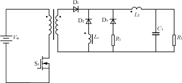

Figure 2 Application of spike suppressor
2.2 Magnetic amplifier
The magnetic amplifier uses the physical characteristics of the controllable saturation inductor conduction delay to control the duty cycle and output power of the switching power supply.
The switching characteristics are controlled by the feedback signal of the output circuit, that is, the switching function of the magnetic core is used to realize the voltage pulse through a weak signal.
Pulse width control to achieve output voltage stability.Add appropriate sampling and control devices to the controllable saturation inductor to adjust its conduction
The delay time can form the most common magnetic amplifier voltage stabilizing circuit.
There are two types of magnetic amplifier voltage stabilizing circuits: voltage type control and current type control.Figure 3 shows the voltage type reset circuit, which includes electrical
Voltage detection and error amplification circuit, reset circuit and control output diode D3, it is a single closed-loop voltage regulation system.
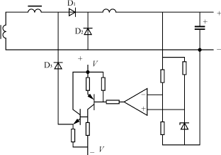
Figure 3 Magnetic amplifier voltage type reset voltage stabilizing circuit
Figure 4 shows the phase-shifted full-bridge ZVS-PWM switching power supply magnetic amplifier regulator.Full bridge switching circuit transformer secondary double half wave
Each rectifier is connected to a magnetic amplifier SR, and its core is wound with a working winding and a control winding.In the positive half cycle, when an output rectifier is forward biased
(The other output rectifier tube is reverse biased), the square wave pulse output from the secondary side of the transformer is added to the corresponding working winding, making the SR core forward
Magnetization (magnetization); in the negative half cycle, the output rectifier is reverse biased, and the diode D3 connected in series with the control winding is forward biased and conducts. Under the action of the DC control current Ic, the core of the SR is demagnetized (reset).
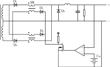
Figure 4 Phase-shifted full-bridge ZVS-PWM switching power supply magnetic amplifier regulator
The working principle of the control circuit is: after comparing the output voltage of the switching power supply with the reference, the gate of the MOS tube is controlled through error amplification.
The MOS tube provides the control current Ic of the magnetic amplifier SR related to the output voltage.
2.3 Phase-shifted full-bridge ZVS-PWM converter
The phase-shifted full-bridge ZVS-PWM converter combines the advantages of zero-voltage switching quasi-resonant technology and traditional PWM technology. The operating frequency is fixed. During the commutation process, LC resonance is used to make the device zero-voltage switching. After the commutation is completed, it still remains It uses PWM technology to transmit energy, has simple control, small switching loss and high reliability. It is a soft switching circuit suitable for large and medium power switching power supplies.But when the load is very light, especially the ZVS condition of the lagging arm switch tube is difficult to meet.Using the saturated inductor as the resonant inductor of the phase-shifted full-bridge ZVS-PWM converter can expand the range of switching power supplies that meet ZVS conditions under light load.Applying it to arc welding inverter power supply can reduce the loss of additional loop energy and effective duty cycle. On the basis of ensuring efficiency, it expands the load range of zero-voltage switching and improves the performance of soft-switching arc welding inverter power supply. reliability.
Connecting the saturated inductor in series with the secondary output rectifier of the isolation transformer of the switching power supply can eliminate secondary parasitic oscillations, reduce circulating energy, and minimize the duty cycle loss of the phase-shifted full-bridge ZVS-PWM switching power supply.In addition, the saturated inductor and capacitor are connected in series to the phase-shifted full-bridge ZVS-PWM switching power supply transformer, and the super forearm switch tube works according to ZVS; when the load current approaches zero, the inductance increases, preventing the current from reversing The change creates the ZCS condition of the lagging arm switch tube and realizes the phase-shifted full-bridge ZV-ZCSPWM converter.
2.4 Resonant converter
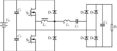
A series resonant converter using a series inductor or a saturated inductor is shown in Figure 5.When the resonant inductor current operates in a continuous state
In the state, the switch tube is turned off at zero voltage/zero current, but it is hard turned on, and there is a turn-on loss.Antiparallel diodes are naturally open
On, but there is a reverse recovery current when turned off. Therefore, the anti-parallel diode must use a fast recovery diode.In order to reduce the switching tube
The turn-on loss is reduced to achieve zero-current turn-on, which allows the switch tube to be connected in series with an inductor or a saturated inductor.Before the switch tube is turned on, the saturated power
The sense current is zero.When the switch tube is turned on, the saturation inductance limits the current rise rate of the switch tube, causing the switch tube current to slowly rise from zero, thereby achieving zero current turn-on of the switch tube, while improving the turn-off conditions of the diode and eliminating the reverse recovery problem. .
2.5 Inverter power supply
Inverter power supply is widely used in automatic control, power electronics and many other advantages due to its good control performance, high efficiency, small size and so on.
and precision instruments and other aspects.Its performance is closely related to the quality of the entire system, especially the dynamic performance of the power supply.because
The characteristics of the inverter power supply itself and its dynamic characteristics have never been ideal.The working principle of an inverter power supply controlled by PWM and PFM determines that in order to obtain a smooth current and voltage waveform, a freewheeling inductor must be added to its output circuit, and this inductor is the main factor affecting the dynamic performance of the inverter power supply.For a constant voltage source, the inductor current is completely inversely proportional to the load; for a controllable constant current source, in order to change the inductor current from small to large, a small load value must be used as the premise. Although it is not a complete correspondence, it can be said Changes in current reflect changes in load to some extent.Therefore, using an inductor that decreases as the current increases as the output inductor of the inverter power supply can effectively change the time constant T of the power supply output circuit, making it completely inversely proportional to R (T=L/R), and then in the load Maintaining a relatively small value within the variation range will naturally improve dynamic performance.